Fingerprint Reader Round 2 (also configured lefty)

This is a follow-up post to my first post about a DIY fingerprint reader. I wanted something smaller, small enough to put on a key chain. In my previous post, I said I was going to try to cram one of my extra laptop fingerprint readers into a dead thumb drive. As it turns out, I had another device just that's slightly larger and fits the reader better.
The devices
I was digging through a drawer of stuff and came across a USB 3G modem. Being slightly larger than a thumb drive, the housing of the device is better suited to the fingerprint reader I purchased.USB 3G Modem (Huawei EC1260)

Fingerprint Reader (Lenovo X60/X60S fingerprint reader)
This is the same device as the one that I used when I put a fingerprint reader in a USB hub, so everything I learned there carried over. One word of warning with this fingerprint reader is that the order of the data lines is swapped. Viewing from the front, the traces coming out in the connector are ordered from left to right as follows: ground, white data, green data, +5v.

The process
| Step 1: | I started by tearing the 3G modem apart. Inside there were two boards, only one of which was actually needed for this project. |  |
| Step 2: | I was going to cut the board, but decided instead just to remove enough components to make it fit. Here are some things that I removed. Particularly, note the right-most components on the bottom side. These must be removed to ensure the data lines are no longer connected to anything else on the board. Running some tests with my multimeter revealed that I had bridged ground and +5v, so I had to fix that. Once I cleaned up the excess solder that I had left behind, ground and +5v were no longer shorted. |  |
| Step 3: | Next, I had to shave just a little off the ends of the fingerprint reader so that it would fit inside the case. It's really so little that it's not visually noticeable. |  |
| Step 4: | Now it was time to solder the fingerprint reader to the board. I cut the lead coming out of the fingerprint reader, and soldered some wire to it. I then disconnected the lead from the fingerprint reader to simplify the process of soldering the other end of the wires to the board. Take note that the data lines are criss-crossed because the data lines coming out of the reader are reversed. Also the metallic area on the board that I've marked in red is ground, so I had to cover this in electrical tape to prevent my device from shorting out. |  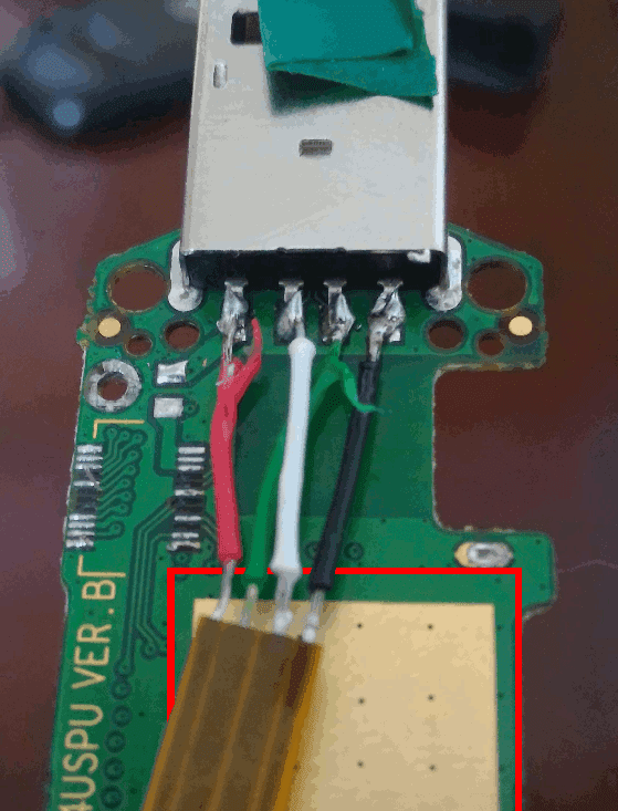 |
| Step 5: | At this point, all I needed to do was to cut a hole in the top of the case for the fingerprint reader to poke through. To do this, I simply took note of about where it was located and made a small hole in the case with a knife. From there, I simply expanded the hole, putting the fingerprint reader in place every so often to see how much more needed to be cut away and from where. Once I had enough cut away, I smoothed the edges that my finger will slide across and I added one, small dab of hot glue to hold the reader in place. |  |
| Step 6: | I snapped the case together, and noticed that the USB moved in and out of the case ever so slightly when pulled or pushed upon, so I opened up the back and put a little glue on the board to hold it in place. |  |
At this point I was finished. I snapped the case back together, and plugged it into my computer. It worked beautifully. Now I can disconnect my fingerprint reader and keep it on my person if I like.


Comments
Post a Comment